


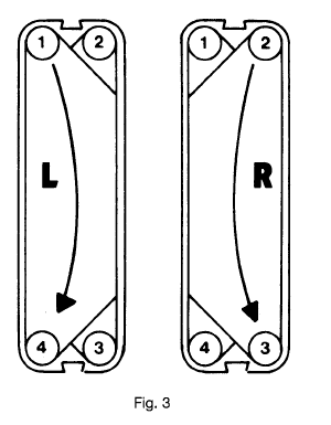
The plates can be used as the left and right plates, which need only be rotated at an angle of 180°.
Left and right panels:
In the left plate, fluid flows from the hole 1 to the hole 4 or from the hole 4 to the hole 1.
In the right plate, fluid flows from the holes 2 to the holes 3 or from the holes 3 to the holes 2. (Fig.3)
Corner hole of the plate
The liquid flows in the plate heat exchanger and it is necessary to open the plate with 4 corner holes. The corner holes are indicated by numbers from the upper left corner of the plate (from the side with the pad), clockwise from 1 to 2, 3, and 4. The angle of the open corners and the flow of liquid in the heat exchanger can be seen from the figure. (Fig.4)
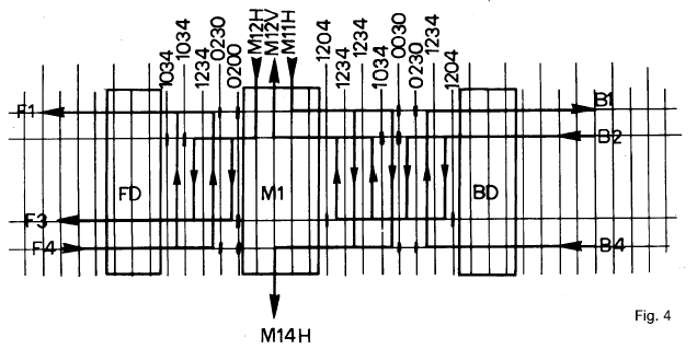
The holes opened in the gusset are described by codes. For example: 1234 means that all corner holes are open. 0204 indicates that 2 and 4 are open, while 1 and 3 are closed.
Replacement plate
The new plate can only be replaced or installed after the clamp bolt is removed and removed. Before installing the spare boards, check to see if they are the same as the one you want to replace. It is also possible to change the number of plates, but the plates need to move two pieces and two pieces, so that the remaining pieces are still left and right. Make sure that the removed plate is fully open with 4 holes. After the change, the clamping dimensions must be adjusted.
Note: The change in the number of plates means that the area of heat exchange of the plate heat exchanger also varies with respect to the change of the plate. A reduction in the sheet will cause an increase in the pressure drop of the plate heat exchanger.